FPQ-6 Tracking and Ranging
Tracking techniques
- Antenna structure
- Tracking and Ranging
- Brief system details
- RCA Computer
- Mission Activity
- Research activity
- BDA, CRO & RCA: Q6 partners
Back to Station Equipment
Contents |
All tracking systems go through four phases of activity for each track - pre-pass checks, acquisition of spacecraft (or satellite), tracking data output, and post-pass checks – except that for a precision radar, such as the FPQ-6, there are additional refinements. [1]
Pre-pass checks
In addition to the usual slew tests and collimation tower tests of reflector and transponder tests, FPQ-6 recorded the local humidity and pressure entered into the RCA computer to compensate for the refraction coefficient which depends on the atmospheric factors in a complex manner and affects the calculation of range. [2]
Acquisition
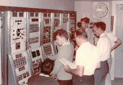
Usually, the FPQ-6 antenna was controlled by the data processor from pre-programmed orbital parameters which provided antenna pointing angles and a ranging distance. If no clear radar signal was received, the console technician would modify the pre-programmed tracking path by choosing an antenna angle scan (usually an 8 mil diameter circle) and a range search (usually pm 10,000 yards either side of the predicted range) or through the station ‘acquisition bus’ by slaving to a station antenna which had already locked onto the spacecraft.
Part of the skill of acquisition required the patience of the technician to allow the spacecraft to move ‘through’ the antenna side-lobe into the main signal lobe before locking onto the spacecraft.
Tracking data output
Once the spacecraft had been acquired, the RCA computer proceeded to update its orbital parameters to provide more accurate orbital data to down range radars and to the data processor should a premature loss of signal (LOS) occur and re-acquisition became necessary. Meanwhile high speed tracking data (10 sets/sec) was recorded on magnetic data and low speed tracking data (1 set/sec) was dispatched by teletype to the tracking network.
Post-pass checks
After LOS a final collimation tower check was made and the local atmospheric data was again recorded to enable possible further adjustments to the tracking data recorded and to the orbital parameters.
Following the Apollo-8 mission, NASA queried a range tracking difference of 60 metres between the Carnarvon FPQ-6 and the Unified S-Band ranging systems at an elevation of about 13 degrees. [2] Local static tower tests and dynamic testing with the STADAN simulation aircraft revealed no significant local differences. [3] Finally Carnarvon engineers suggested that NASA had applied the FPQ-6 refraction coefficient in the US in addition to its automatic inclusion at Carnarvon. The station heard no more about the ‘error’.
Ranging
The FPQ-6 Digital Ranging Machine [4], an extended version of the FPS-16 system, used nth-time-around techniques to achieve a maximum unambiguous range of 32,768 nautical miles (60,686 Km) with a precision (accuracy) of ±2 yards (1.8m). The FPS-16 standard radar had only a maximum range of 500 nautical miles with a precision (accuracy) of ±5 yards although later it was modified to 5000 nautical miles as could be the FPQ-6 radar to 256,000 nautical miles.
The concept of precision/accuracy needs clarification. Lindsay Sage, an early Chief Engineer of the station, is remembered as saying, “You can be very precise and be precisely wrong”. Precision is the closeness of the individual readings to each other and is nothing to do with how accurately – how close - they are to the true value. Accuracy depends on other factors apart from the structural integrity of the antenna. [5] (read more 'Accuracy' detail)
MSFN spacecraft were normally tracked in ‘beacon mode’ where the spacecraft transponder replied to a coded pulse group from the radar (typically two pulses 3 μsec apart) responding with one pulse generally of a different frequency to that of the interrogation. The ‘total trip time’ from the ground radar to the spacecraft and back again is used to calculate the range of the spacecraft. (read more 'Range' detail)
In ‘skin mode’ where the signal is passively reflected from the spacecraft’s metal skin, the FPQ-6 could acquire and track a 1-metre square target at a range of 500 nautical miles and hold that track out to approximately 600 nautical miles.
“The receiving system provides simultaneous presentation of the skin and beacon returns to the console operator so that skin track can be used in the event that the beacon signal is lost.” [6]
Angles system
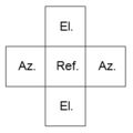
"The radar employs a 2.8-megawatt peak power (4.8 KW average), broad-banded (5400 to 5900 MC) transmitter with frequency stability of 1 part in 108. The 29-foot diameter antenna dish uses a Cassegrainian feed and has a 51 DB gain with a 0.4-degree beam width. Its monopulse, 5-horn feed system permits the reference and error antenna patterns to have their gains independently established as well as the slope of the error patterns optimized while supplying target return signals to the receiving system with a minimum of feed insertion loss." [6] (read more 'Angle' detail)
"This design has advantages over conventional monopulse feeds and reduces the possibility of side lobe lock-on. The three-channel signal outputs of the antenna feed system [Az., El., and Ref.] are supplied directly to the receiving system without undergoing any additional, loss-inducing, signal manipulation. The three-channel monopulse receiving system has its bandwidths optimized for the specified pulse widths of 0.5, 0.75, 1.0, and 2.4 microseconds, and the receiver noise figure of 7.5 DB has been improved to 3.5 DB through the addition of closed-cycle, parametric RF amplifiers." [6]
Angle pointing accuracy is 0.1 mil (0.005625°)
Side-lobe detection
Although the 5-horn feed supposedly reduced the chance of locking onto a side lobe, a small auxilliary side-lobe dish was later attached to the rim of the FPQ-6 dish to detect such an occurrence Its use at Carnarvon seemed unnecessary as the main lobe was easily acquired so the auxiliary dish was rarely switched on. The FPQ-6 team thought it could only be useful to a radar near the launch site and consequently nearer the spacecraft.
“In the case of a radar like Q-6, track on a [broader beam] side-lobe is very sloppy and the antenna sort of waggles around the true direction in a non predictable manner. In order to detect the main lobe, the computer drives the antenna in a circular path around the actual track with a radius of 1 or 2 degrees in the hope that, in the process, the main reflector will intercept the main lobe which will be detected by the difference in signal strength ... When it does intercept the main lobe, the system will break track on the side-lobe and acquire the main lobe. Due to the rather esoteric nature of the theory, the side-lobe system was distrusted by certain members of the Q-6 team and it was never used until on one mission, someone forgot to disable it and the Q-6 acquired a side-lobe and, a few seconds later, the antenna started the circular motion (and caused great consternation in the team standing in front of the console) and it accurately acquired the main lobe.” [7]
Bob Hocking recalls: “On at least two occasions the small dish became detached. I think once it hung from its coaxial cable. The other time it was found on the ground. No one noticed it was missing. During servo bandwidth tests it took a fair hammering. I attached a label to the function generator amplitude control marked ‘Side-lobe Dish Jettiron’. Later Dave Gardiner put a patch in the Real Time Program’ and through a bit of my hardware [it[ killed the servo drive and applied the brakes, This was known as the anti-Kloppenburg device.” [8] An application for this engineering change was never made.
References and Notes
[1] Anderson, K. and Hocking, R. personal communications, 2005
[2] Heald, B. personal communication, 15 October 2005
[3] NAA: PP583/1 C358A, Contractor Performance Report, June 1969
[4] ‘machine’ - a heritage of the days of mechanical control rather than digital electronics
[5] Housley, T. email, 22 August 2005
[6] Technical Information Bulletin, GSFC, MSFN: Vol.1 No.11; July 26, 1963
[7] Housley, T., email 26 August 2005
[8] Hocking, B., email 25 August 2005


